Water Pressure
(bar) |
Orifice/hole(mm2) |
Water capacity
(l/sek) |
Water capacity
(l/month) |
Water capacity
(m3/month)
|
Water capacity
(m3/year) |
|
5 |
0,5 |
0,006 |
0,36 |
15,8 |
189 |
|
1,0 |
0,016 |
0,96 |
42,0 |
504 |
|
5,0 |
0,372 |
22,32 |
977,1 |
11 725 |
|
10,0 |
1,406 |
84,36 |
3 692,9 |
44 315 |
|
10 |
0,5 |
0,008 |
0,48 |
21,0 |
252 |
|
1,0 |
0,023 |
1,38 |
60,4 |
725 |
|
5,0 |
0,497 |
29,82 |
1 305,4 |
15 665 |
|
10,0 |
1,989 |
119,34 |
5 224,2 |
62 691 |
|
16 |
0,5 |
0,010 |
0,60 |
26,3 |
315 |
|
1,0 |
0,029 |
1,74 |
76,2 |
914 |
|
5,0 |
0,629 |
37,74 |
1 652,1 |
19 825 |
|
10,0 |
2,515 |
150,90 |
6 605,8 |
79 270 |
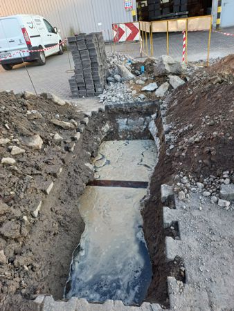
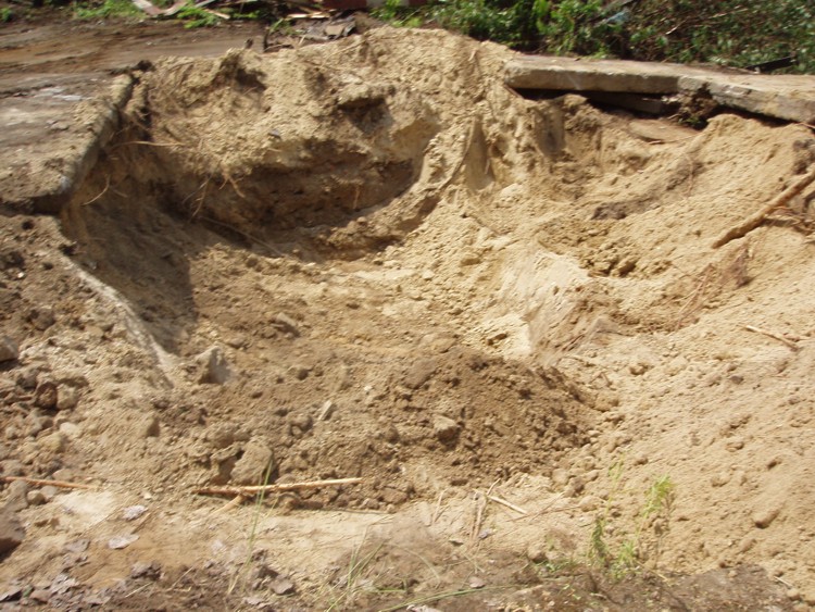
LOCATION OF WATER LEAKAGES FROM METAL AND NON-METAL WATER SUPPLY
NETWORKS
Leaks in pipelines: metal, plastic,
asbestos or concrete are located in pipes filled with water under
pressure of at least 2 bar (0.2 MPa = 2at).
A diagram or sketch of the water supply and sewage system must be
submitted for review.
 Research techniques used.
The following activities are used to locate hard-to-detect water leaks:
Listening with a rod microphone for available elements of the water
pipeline
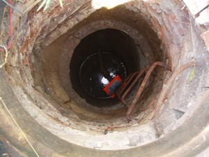
There is needed access to:
water supply wells, hydrants, earth gates, etc..
In special cases, rooms should be made available in buildings where the
water supply connection to the building is visible.
Attention:
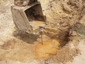
- Prior excavation by the service provider is necessary, as far as
possible
possibilities, any buried water supply wells, gate valve boxes
earthworks, etc..
Current practice in the field of pipeline testing performed by
The Wodoserwis company shows that instead of locating water leaks
on networks, time is unnecessarily used for localization
and unearthing wells or earth gate boxes lost in the field
waterworks.
Correlation (location) of
pipeline leaks using a correlator and microphones (accelerometers) or
hydrophones.
Correlation for metal or non-metal pipelines.
Equipment used:
Microphones/accelerometers
If the length of the tested non-metallic pipeline (or cast iron) exceeds
100 – 120 meters and there are no available elements
water pipeline along this length. The person ordering the service is obliged
to make open pits of the pipeline every 30 ÷ 100 meters in order to
installation of steel clamps for the pipeline by Wodoserwis.
Clamps allow you to attach sensors/accelerometers to a non-metallic
pipeline.
Note: If the non-metal pipeline is equipped with hydrants, it is not
necessary to perform the above-mentioned work. excava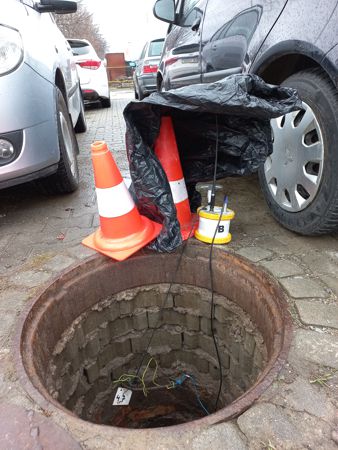 tions.
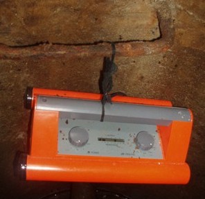
Hydrophones
Hydrophones are screwed to the "external" or "internal" hydrant sockets or
to other available intake valves (if there are no hydrants) to which
you can tighten the hydrophones.
An employee operating the water supply network, authorized to unseal and
open ground or above-ground hydrants, is required,
to which the hydrophones will be screwed.
In addition to the hydrant wrench, you need a key for the hydrant shut-off
valve.
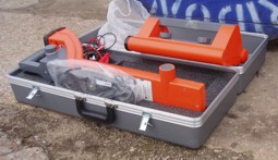
Correlation of pipeline
leak locations using a correlator and multisensors (acoustic recorders),
optional method.
The multisensors are equipped with very sensitive piezoelectric microphones
with an amplifier, data memory, a battery and a radio module with an
antenna.
Depending on the environmental conditions, multi-sensors are left on the
pipelines at night.
Multisensors are used optionally, as needed.
It is possible to perform correlation measurements on pipelines equipped
with steel or cast iron elements located at very great depths.
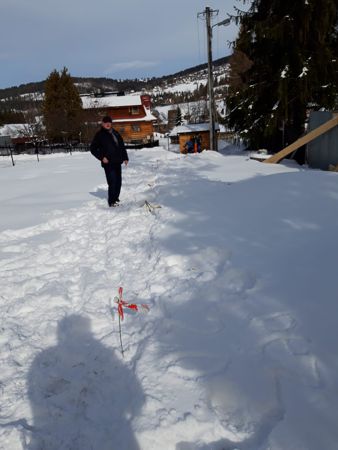
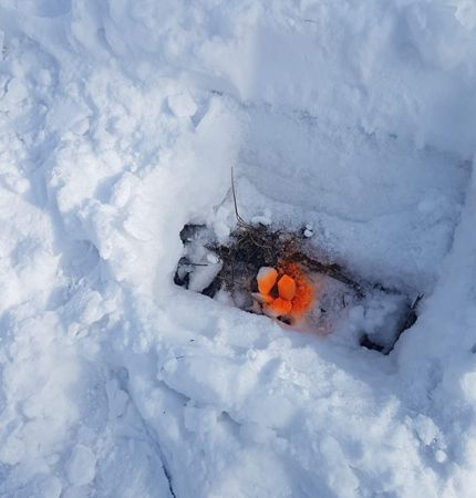
Listening to the ground above the pipeline with a geophone (and possible
sound analysis with specialized software).
Auscultation with a geophone of the surface above the pipeline with a
confirmed, probable leak location in order to precisely locate the leak.
Quick physicochemical analysis of water to immediately recognize the type of
water
- when locating places of water leaks, depending on the needs, water
occurring in the field, in the area of the pipeline, is collected and
analyzed
(sewerage, ditch, ground surface, tunnel, etc.).
The quality of water taken from the area is compared with water from the
tested pipeline.
For water supply companies interested in the issue of searching for water
leaks from pipelines, the Company has developed a several-page GUIDE, .PDF
format, entitled: "Problems of reducing water losses in water supply
networks" - available for download on the Company's website.
Problemy
ograniczania strat wody w sieciach wodociągowych - Poradnik ,
format .PDF .
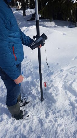
MONITORING OF WATERWORKS

The company offers monitoring of
the water supply network.
Measurements of water flows and pressure in pipelines, measurements of water
levels.
Solutions in the system of wired and wireless transmission/registration of
energy media network parameters to the computer of the unit on duty.
Advantages of monitoring:
- reducing water losses in the water supply network by quickly locating
leaks
- improving the functioning of supervision over the water supply network
- improving process control
- reducing and automating the operation of networks and technological
facilities
- improving the safety and reliability of devices
Registration of water flows with a programmable recorder for connection to
flow meters and transmitters (2 inputs 0/4-20 mA, 2 PULS inputs), ability to
display up to 4 measurement channels.
- Simultaneous recording of additional other parameters of the water supply
system (e.g. pressure, level)
- Instantaneous flow rate readings
- Determining extremes (minimum and maximum threshold values)
- Flowmeter operating time counter
- Archiving results on a computer using a card and specialized software
- Data averaging
- Graphical and tabular presentation of results
- Print reports
The new
a data logger specially designed for the needs of water
suppliers. The logger is battery powered which lasts for 5 years
even with integrated GSM/GPRS module. This unit is available in
several configurations with internal sensors and various input
channels.
Wireless
programming and read out:
Yesterday was the time to connect each logger with a cable to
program or to read data. In combination with the PC radio
interface USB-E-box one can simply program several loggers one by
one via radio. The read out process works the same if you use the
Reader Box. Simply go near by the logger (radio range up to
20m and more) and collect all data stored in the internal memory of
the logger. Transfer the data later to your PC and do your
analysis.
Recording:
How ever
your recording interval should be: you simply program the loggers
for your special needs. From 1 sec. up to 31 days an interval can be
chosen. The huge internal memory of the logger saves data up to 28
years and if this is not enough one can simply upgrade the memory
with standard SD/MMC cards.
Sensors:
This unit is available with integrated pressure sensors or
simply as a “regular” data logger. All 0-5V or 0-20 mA sensors can be
attached and the data can be logged. The accuracy is certainly
± 0.1%.
Telemetry data logger:
As a special version the device comes with an integrated
quad-band GSM/GPRS modem to transmit data over a long distance.
Data are provided via FTP to easily integrate the data into
existing telemetry systems.
Alarming:
Each channel has individual alarm thresholds. Once this threshold is
reached the logger sends a SMS or message to the telemetry
system.
LOCATION OF WATER AND SEWAGE UTILITIES
ROUTING - LOCATION OF PIPELINES
Metal pipelines
- Detection of network routes and connections up to a depth of 6 m.
- Determining the depth of installation of pipelines in the ground.
To locate metal pipes (steel, cast iron), a locating kit equipped with a
pulse generator is used - connected to
available pipeline element.
Each time, the maximum pipeline routing range is up to 150 meters in both
directions from the access point, i.e. 2 x 150 meters = 300
meters.
If there are no available pipeline elements, it is possible to locate the
pipeline using another method without measuring the depth of the metal
pipeline foundation.
Non-metallic pipelines made
of:
- plastics
- concrete, asbestos, cast iron
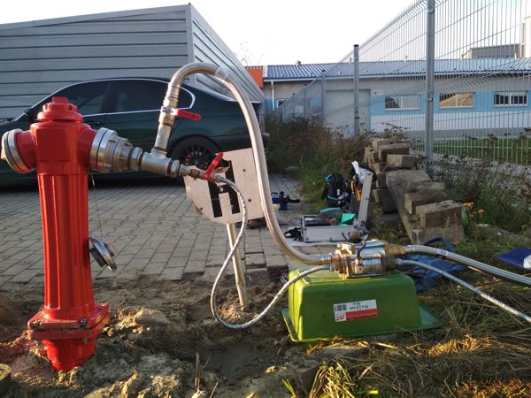
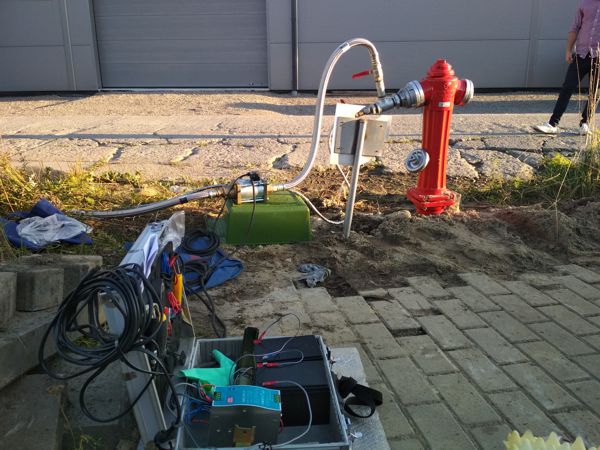
To locate the route of pipelines filled with water, Wodoserwis uses its own,
innovative technical solution
on generating small water hammers (smaller or larger - depending on needs)
in the tested pipeline and listening to the ground,
thus identifying the pipeline route.
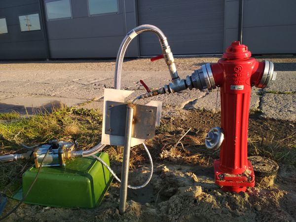
A connection to the pipeline via a hydrant or a building tap is used here.
When creating shocks, water is thrown into the area or into the sewage
system.
If a hydrant is used, the service ordering party must provide a person
authorized to open hydrants.
In the case of an earth hydrant, an appropriate hydrant stand must be
prepared.
Each time, the maximum routing range of the tested pipeline is approximately
100 meters on both sides of the pipeline from the production site.
water hammer, i.e. up to approximately 200 meters of the routed pipeline.
Attention:
it is possible to locate plastic pipelines if the pipeline was laid with
a metal tape or signaling cable for the purpose of later locating the
pipelines using
locator cooperating with the signal generator.
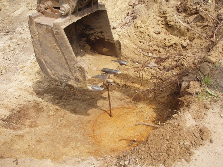
LOCATION OF METAL: MANHOLE COVERS, GATE
BOXES, HYDRANT BOXES, VALVE STYLES, etc.
The devices used by Wodoserwis enable the
location of metal (steel, cast iron) elements of water and sewage
infrastructure - fittings, manhole covers,
gate valve stems to a depth of 2.5 meters.
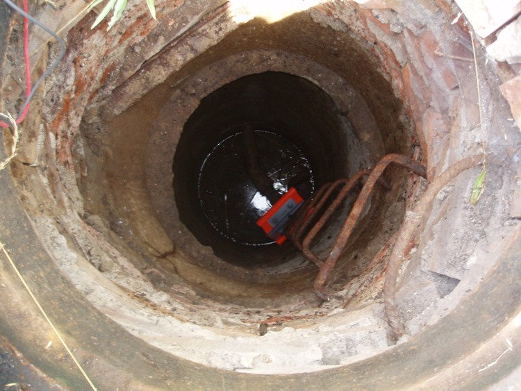
If instead of a metal cover, a reinforced concrete cover was placed on
the well manhole, the locator will detect the reinforcement of this
cover.
A buried water or sewer well that is located at the junction of a metal
water or sewer main will be located
to a depth of 6 meters by locating water supply or sewage network
routes.
If the earth gate valve box is lost in the field, it is possible to
locate the gate valve stem, even if the stem diameter is only 10 ÷ 15
mm.
Inspection of hard-to-reach places with a
micro-inspection camera
- lens housing diameter: 17 mm
- monitor diagonal: 52 mm
- cable length: up to 6.5 m
- intended use: pipes, tunnels, mini windows with a diagonal of up to 50
- 80 mm
- the camera can work underwater up to a depth of 3.0 m
Photos Gallery

return up ↑
WATER CONSUMPTION STANDARDS
In Poland water consumption
standards are regulated by the "Regulation of the Minister of Infrastructure
of January 14, 2002 on determining average water consumption standards"
(Journal of Laws No. 8 of January 31, 2002 - Item 70):
The recommended standards
for water consumption in Poland
Normy zużycia
wody reguluje "Rozporządzenie Ministra
Infrastruktury z dnia 14 stycznia 2002 r. w sprawie określenia przeciętnych norm zużycia wody"
(Dziennik Ustaw nr 8 z dnia 31 stycznia 2002 r. - Poz. 70)

The regulation contains average water
consumption standards for the following groups of recipients:
Household
Watering home gardens and agricultural crops
Services, Farms and livestock facilities
Servicing motor vehicles, agricultural machinery and workshops
Agricultural and food processing plants
Works
Chemical plant protection
Military facilities of the ministries of defense and interior affairs
However, there are another detailed recommended standard the water
consumptions based on technical documentary or operator’s
manual etc. as given below.
Other detailed, individual water
consumption/demand are resulting from technical documentation or
technology.
|
 |
|
.
Another detailed standards water consumption
Air Conditioning
Air Conditioner type KT 2.1
Condenser cooled water temperature: 12 o C, water capacity: 400 l/h, inside
diameter d= 15 mm.
(based on air conditioner KT 2.1 documentary – Germany, VEB Maschinen und
Apparatebau Schkeuditz)
Another type KT:
KT 4: 350 l/h
KT 4.1: 420 l/h
Type CAS (Clivet - Italy), ex: CAS 51: 1 800
l/h
Type K 3 300: 200 l/h
Laboratories

The water consumption in laboratories (data based on installation
documentary):
a
polish water re-distiller type REL 5 (capacity 5 l/h) - consumption
150 l/h
a
polish water distiller type DEM 10 (capacity 10 l/h) - consumption
85 l/h, type DEM 5 (capacity 5 l/h) - consumption 42 l/h
Bakeries

The water intake only for dough production (the water intake as a raw
material without sewage for sewage system)
1. The dough production:
100 kgs flour needs 50 l water, it means that 1 kg the flour needs 0,5 l water
2. Steam production in baking oven:
Medium size baking oven needs 870 l water per day
3. Water consumption for steam in steam pot:
1 steam pot needs 1 000 ls the water per month
(Information comes from bakery’s owner in Krakow city consuming 98 600 kilograms
of flour a month. Eight tenth of this flour is used for bread and the rest for
sweet croissants and doughnuts).
According to “Rozporzadzenie Ministra Infrastruktury z dnia 14 stycznia 2002 r.
w sprawie okreslenia przecietnych norm zuzycia wody (Dziennik Ustaw nr 8 z dnia
31 stycznia 2002 r. - Poz. 70)”, all in all the bakery needs: 2,0 m3 the water
for 1000 kg bread, it means that 1 kg bread needs 2 l the water.
Canteens
 (based on
the Polish book: "Wyposazenie stolowek w zakladach przemyslowych" -
author: Z. Mirski) (based on
the Polish book: "Wyposazenie stolowek w zakladach przemyslowych" -
author: Z. Mirski)
the water for handy dishes washing: 7,5 l for 1 meal
the water for dinner: 30 l/dinner (the first course and main course altogether)
the water for worker regenerative meal: at the table - 15 l/meal, take away meal
- 7,5 l/meal.
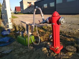
Hydrants 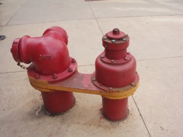
Outdoor hydrants
In the fire-fighting water supply network, mainly external above-ground
hydrants with a nominal diameter of DN 80 are used.
The nominal capacity of an external fire hydrant at a nominal pressure
of 0.2 MPa (2 bar) measured in the hydrant valve during water intake for
a DN 80 hydrant should be at least 10 dm3/s.
Regulation of the Minister of Internal Affairs and Administration of
July 24, 2009 on fire-fighting water supply and fire routes (Journal of
Laws No. 124 - Item 1030).
In the Regulation, at least:
- Types of facilities requiring fire protection water supply for
external fire extinguishing
- Methods of determining the required amount of water for fire
protection purposes
- Fire protection requirements for water supply networks
- Fire pumping stations
- 4 tables regarding the required amounts of water for fire protection
purposes for settlement units and facilities
Internal hydrants
Regulation of the Minister of Internal Affairs and Administration of
June 7, 2010 on fire protection of buildings, other structures and areas
(Journal of Laws No. 109 - Item 719).
Minimum water intake efficiency measured at the nozzle outlet:
for hydrant 25 - 1.0 dm3/s
for hydrant 33 - 1.5 dm3/s
for hydrant 52 - 2.5 dm3/s
for valve 52 - 2.5 dm3/s
In the Regulation, at least:
- maximum working pressures in the fire-fighting water supply system
- number of simultaneously operating hydrants
- capacity of fire protection tanks
- nominal diameters of power cables
Car dismantling stations
 Car
washing: Car
washing:
- passenger: 150 l/1 washing (according to the above-mentioned
"Regulation")
- delivery van: 500 l/1 washing (according to the above-mentioned
"Regulation")
Water demand to keep streets and squares clean:
- for effective one-time mechanical washing of streets and squares: 2
l/m2 of improved surface.
Basis: "Guidelines for programming water demand and the amount of sewage
in urban settlement units" - Ministry of Administration, Land Management
and Environmental Protection. Department of Public Utilities. Institute
of Environmental Management - 1978
At one of the car scrapping stations in Krakow with:
- parking lot for 20 parking spaces with an area of 350 m2
- a scrap yard with an area of 330 m2
water consumption is from 15 to 23 m3/month
 Vehicles
cleaning the water and sewage system Vehicles
cleaning the water and sewage system
- without water recovery systems
Manufacturers' names, capacities of high-pressure pumps:
1. Dobrowolski 265 or 315 dm3/min
2. Else 291 - 942 dm3/min
3. HAKO Polska 120 dm3/min
4. INTEGRA 90 - 500 dm3/min
5. Interglobal 470 dm3/min
6. KANRO 70 - 210 dm3/min
7. MWM Brzesko 90 -500 dm3/min
8. REMO FPHU up to 500 dm3/min
9. UNIMARK 40 - 500 dm3/min
10. WUKO 216 - 406 dm3/min
Basis: Data from the magazine Wodociągi i Kanalizacja 9/2011 (article:
"Report - operating equipment of water and sewage networks")
With:
- parking lot for 20 parking spaces with an area of 350 m2
- a scrap yard with an area of 330 m2
water consumption is from 15 to 23 m3/month
front page
←
return up ↑ |
PIPELINE TIGHTNESS TESTING REGULATIONS
Pipeline tightness testing
regulations (as of 2006)


How to perform a pipeline/installation leak
test
- tightness test
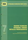
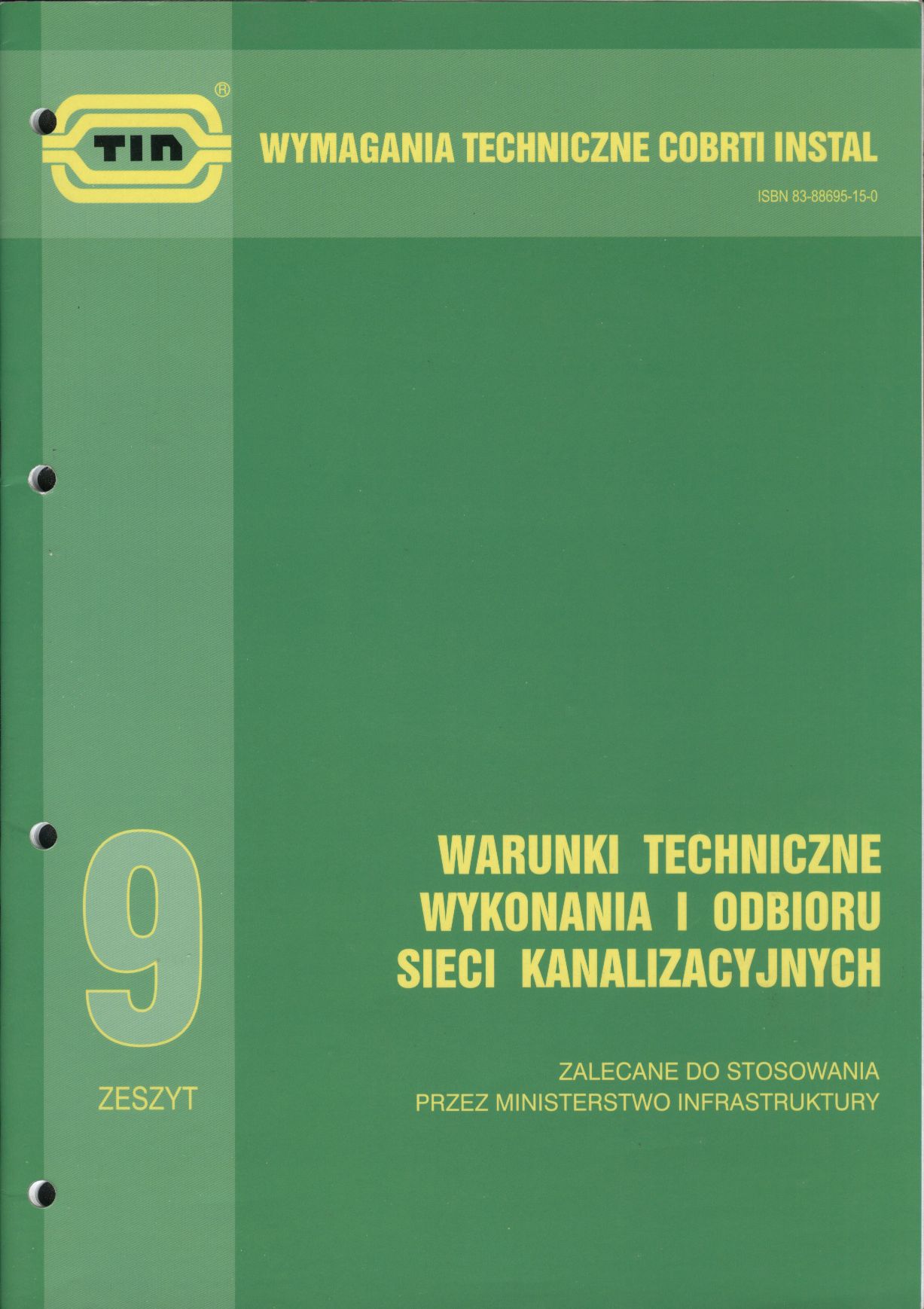
General technical conditions for the execution and acceptance of
water supply networks and water supply installations - technical
requirements, developed on the basis of applicable regulations by the
Central Research and Development Center for Installation Technology
INSTAL (COBRTI INSTAL) - volume 3, volume 7, recommended for use by the
Ministry of Infrastructure.
Comments:
The test should be performed before
covering the installation; if it is required to cover part of the
installation, separate tests should be carried out as part of partial
acceptance tests.
A pressure gauge with a reading accuracy
of 0.1 bar should be connected to the installation.
The test procedure is different for metal
pipes and plastic pipes.
In the case of plastic pipes, the
procedure is longer and more complicated due to the fact that the
pressure drop recorded on the manometer does not have to be the result
of leaks, but results from
initially due to the flexibility of the cables.
The examination is divided into preliminary and main examination
(conducted immediately after a positively completed preliminary
examination).
The preliminary test consists in increasing the pressure to the test
pressure three times every 10 minutes, and then observing the
installation.
for ½ hour
The test is considered successful if there are no leaks or condensation,
especially at the connections, and the pressure drop is less than 0.6
bar.
The main test consists of raising the pressure again to the test
pressure and observing the installation for 2 hours. The test is passed
if there are no leaks
and dew, and the pressure drop is not greater than 0.2 bar.
Therefore, in the case of plastic installations, the pressure gauge
readings are an auxiliary element and significant pressure drops are
allowed.
To properly check the installation, it is necessary to observe the
connections to see if they show any leaks.
The air test pressure should not exceed 3 bar.
Installers sometimes, by mistake, use the pressure as for the water
test, i.e. most often 6 bar for central heating installations and 10 bar
for water supply installations.
After the test, a test report should be prepared specifying the test
pressure and test results.
COBRTI INSTAL notebooks provide a template of the Leak Test Protocol.
Recipes according to COBRTI INSTAL:
Water networks:
1. The test pressure in the networks should be 1.5 times the working
pressure, but not less than 1 MPa (10 bar).
2. The tightness of the pipe should ensure that the test pressure is
maintained for a period of 30 minutes during the hydraulic test.
Water installations:
Leak test should be carried out with water. During partial acceptance of
installations, in justified cases, it is allowed to perform a tightness
test using compressed air.
Water tightness test
1. The test pressure in the networks should be 1.5 times the working
pressure, but not less than 1 MPa (10 bar). The test pressure is
the pressure at the lowest point of the installation at which the test
is carried out testing its tightness.
2. Cold water tightness testing of metal water supply installations
consists of a main test (the pressure cannot drop by more than 2% for 30
minutes), and in the case of plastic pipes
artificial from the preliminary and main tests (the pressure must not
drop more than 0.2 bar for 2 hours).
Air tightness test
1. The pressure value for testing the tightness of the installation with
compressed air should not exceed 3 bar.
2. The condition for recognizing the test results as positive is that
there is no leakage in the installation and the manometer does not show
a pressure drop.
Note: issue no. 6 COBRTI
INSTAL concerns the technical conditions for the execution and
acceptance of heating installations
In the case of a central heating installation, the test pressure should
be 2 bar + working pressure at the lowest point of the installation, but
not less than 4 bar for a radiator installation and 9 bar for a surface
installation, i.e. floor or wall.
This is due to the fact that pumps with a higher lifting height are used
in underfloor heating due to much higher flow resistance in the
installation.
Tightness testing of a water pipeline
or water installation - acceptance tests according to the following
standards:
Waterworks - External pipes
1. "Requirements and tests": PN-B-10725:1997
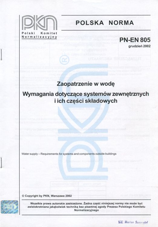
2. "Water supply - Requirements for external systems and their
components": PN-EN 805: 2002, PN-EN 805: 2002/Ap1
It is recommended that the test procedure be determined by the designer.
The procedure should include three stages: preliminary test, pressure
drop test, main pressure test: water loss method or pressure loss
method.
Tightness testing of water tanks -
acceptance tests according to the following standards
Waterworks and sewage
- "Tanks. Requirements and tests": PN-B-10702:1999
- "Water supply - Requirements for systems and their components intended
for storing water": PN-EN 1508: 2002
- "Unpressurized tanks. Requirement: PNs and tests"-B-73001:1996
- "Pressure tanks. Requirements and tests": PN-B-73002:1996
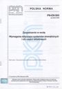
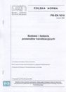
Sewerage tightness testing - acceptance
tests according to the standard:
- "Construction and testing of sewage pipes": PN-EN 1610: 2002, PN-EN
1610: 2002/Ap1
 For
services operating water supply systems, Wodoserwis suggests the
following method of testing the tightness of the pipeline without a
pressure test.
For
services operating water supply systems, Wodoserwis suggests the
following method of testing the tightness of the pipeline without a
pressure test.
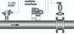
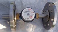
Thanks to a specially made reduction, it is possible to install an
accurate, high-class DN15 control water meter on
connections/installations regardless of the diameter of the existing
water meter and the type of connection between the flow meter and the
pipe.
For flange connections, the minimum length of the measuring system:
control water meter + reduction with flanges is 180 mm - 190 mm, which
allows for trouble-free installation of a flow meter in place of a water
meter, e.g. with a diameter of 50 mm (with an installation length of 200
mm).
front page
←
return up ↑
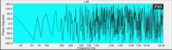
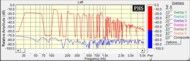
VIBROACUSTICS
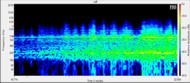 Measurements of machine vibrations and
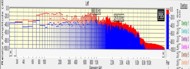
material noise, FFT spectrum
Measurements of machine vibrations and
material noise, FFT spectrum
Vibration measurements
Amplitude units:
- acceleration: g, m/s2
- speed mm/s
- offset: mm
Low frequency range: 10 Hz - 1,000 Hz (determining e.g. general machine
condition)
High frequency range: 4,000 Hz - 20,000 Hz (determining bearing condition)
Example applications:
- diagnostics of operating devices (including bearings: pumps, engines,
etc.) and early detection of their dysfunctions using a patented
measuring instrument algorithm for high-frequency measurements.
Assessment of the level of significance for engines, cooling towers, fans,
cooling tower drives, centrifugal pumps, positive displacement pumps,
air compressors, blowers, gears and spindles.
Fast response in the initial stage of failure in the noise phase, before the
appearance of the vibration and thermal phase of pump elements
and engines, allows you to protect the device from the need to replace the
main components of the device.
 Early detection of damage significantly reduces repair costs and production
interruptions.
Early detection of damage significantly reduces repair costs and production
interruptions.
Three types of measurements: bearing vibration, total vibration and
temperature.
- pipeline vibration measurements, requirements according to manufacturers
of precision devices and measuring systems:
Flowmeters:
- differential pressure transducers (admissible values: frequency level
10-60 Hz, vibration ampl. 0.21 mm/60-2,000 Hz, acceleration ampl. 3g)
- Annubar averaging tubes (admissible values: frequency level 10-1,000 Hz,
vibration amplitude 0.15 mm, acceleration amplitude 2g)
Blood pressure monitors/thermometers:
- pressure/level/temperature transmitters (examples of permissible vibration
values: 4g, (10 - 2,000 Hz)
- protection analyses.
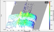
Example applications:
- measurements of pipeline sound emissions caused by high flow, no flow or
other factor
- noise measurements of machines and vibroacoustic devices, industrial
equipment, building infrastructure
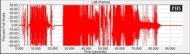
Structure-borne noise measurements
Measurements with a piezoelectric microphone in a wide range of frequency
levels /Hz/.
FFT spectrum recordings of sounds
Pipes and machines vibrations - analysis
Vibration Meter
Sensitivity: 100 mV / g ±10 %
Measurement Range: 0.01 g to 50 g
Frequency Range:10 Hz to 1 000 Hz and 4 000 Hz to 20 000 Hz
Resolution: 0.01 g
Accuracy: at 100 Hz: ±5 % of measured value
Amplitude
Units:
Acceleration: g, m/sec2
Velocity: in/sec, mm/sec
Displacement: mils, µm
Quick Measurement
Overall Vibration (Low Frequency) Measurement with Severity Scale
Crest Factor+ (High Frequency Measurement in bearings)
Interpret Results:
Trending
Vibration Severity - ISO 10816-1
Data transfer
between the Meter and PC. Export Meter
data to an MS Excel spreadsheet
 Company history: the beginnings of the business date back to 1992,
when it specialized in, among others, in the sale of self-closing
sanitary fittings and industrial nozzles for splashing and spraying
liquids.
Company history: the beginnings of the business date back to 1992,
when it specialized in, among others, in the sale of self-closing
sanitary fittings and industrial nozzles for splashing and spraying
liquids.
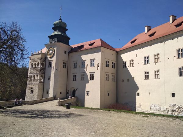
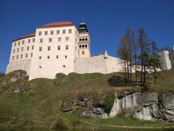


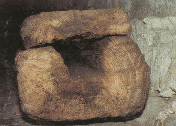
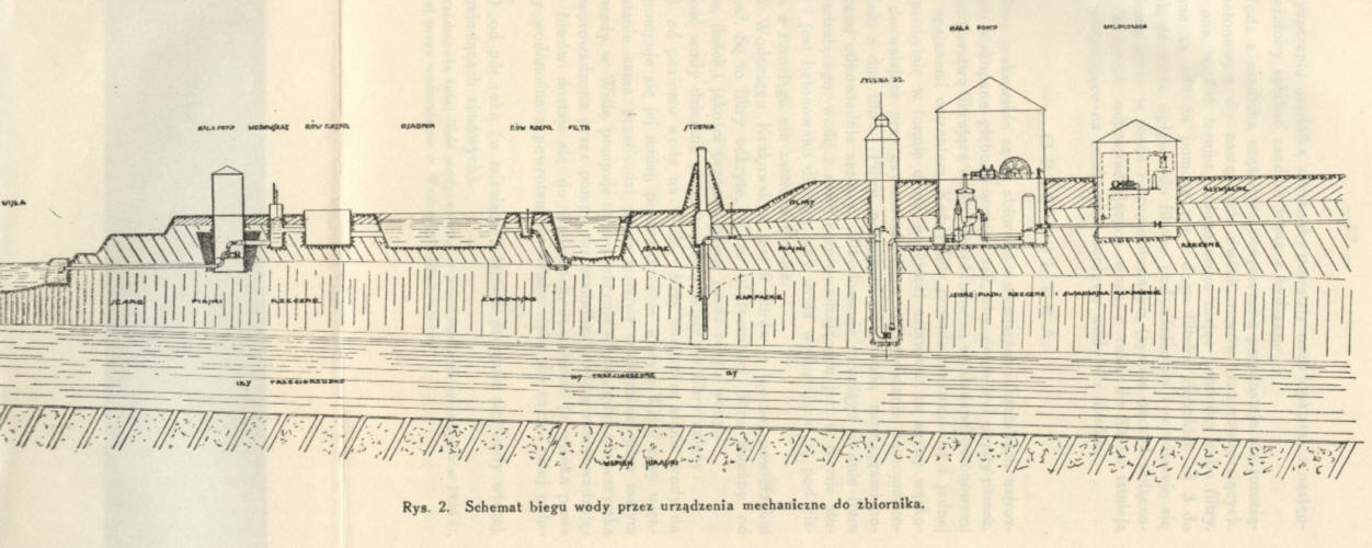
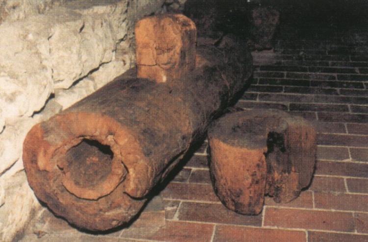
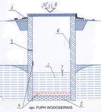
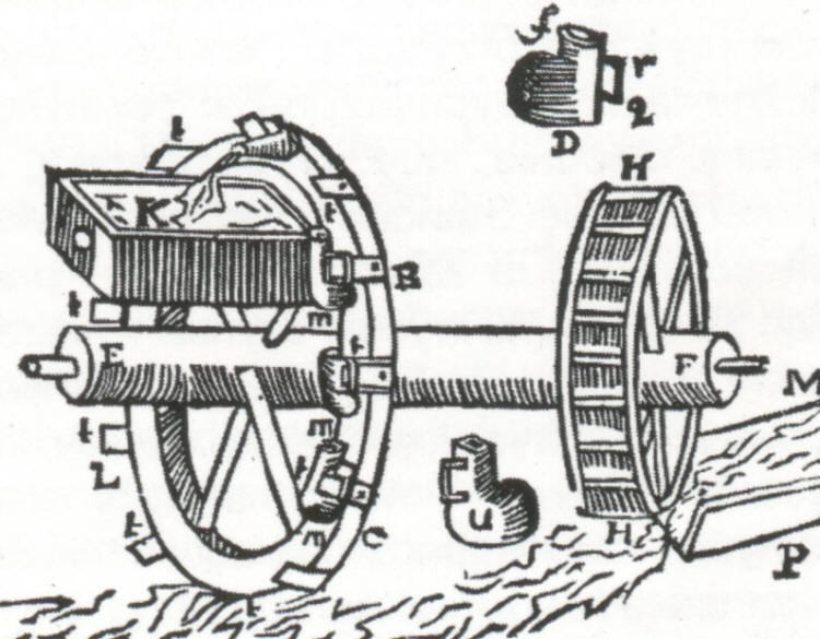 the beginning of the 15th century, waterworks were introduced
with water flowing under low pressure. Water was lifted from the river to a
higher reservoir providing this
the beginning of the 15th century, waterworks were introduced
with water flowing under low pressure. Water was lifted from the river to a
higher reservoir providing this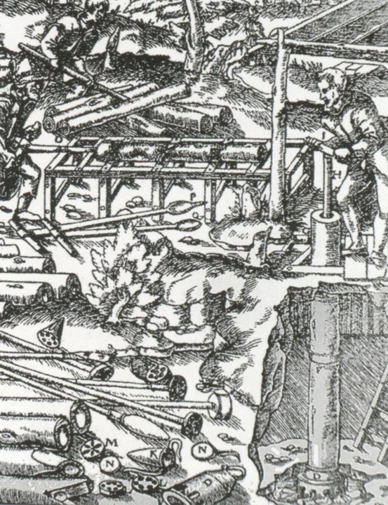
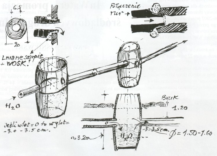

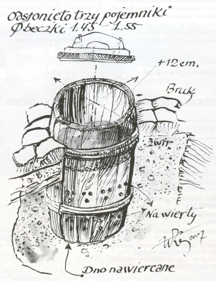

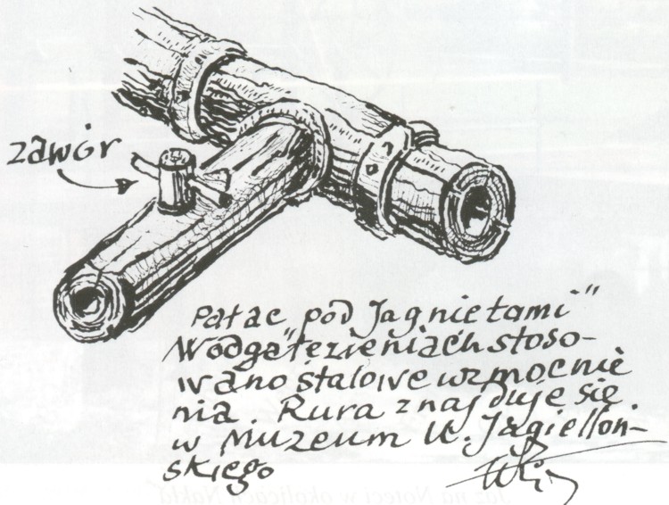 The
drawings of the discovered elements were made by prof. Wiktor Zin during
research on the Krakow market in the 1970s.
The
drawings of the discovered elements were made by prof. Wiktor Zin during
research on the Krakow market in the 1970s.